3-bit Asynchronous Counter
By gyaanibuddy_admin,
This is '3-bit Asynchronous Counter' assignment of Digital Design - Computer Engineering of Somaiya University - Gyaani Buddy
AIM: Design of 3 bit asynchronous counter using JK flip flop
This is '3-bit Asynchronous Counter' assignment of Digital Design - Computer Engineering of Somaiya University - Gyaani Buddy
Coming Soon...
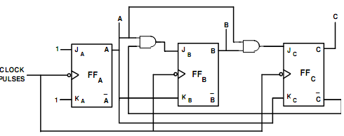
A counter is a register capable of counting number of clock pulse arriving at its clock input. Counter represents the number of clock pulses arrived. A specified sequence of states appears as counter output. This is the main difference between a register and a counter. There are two types of counter, synchronous and asynchronous. In synchronous common clock is given to all flip flop and in asynchronous first flip flop is clocked by external pulse and then each successive flip flop is clocked by Q or Q output of previous stage. A soon the clock of second stage is triggered by output of first stage. Because of inherent propagation delay time all flip flops are not activated at same time which results in asynchronous operation.
Implementation Details:
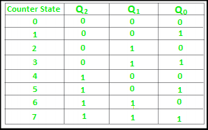
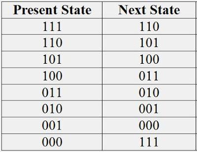
Truth Table for 3 bit UP counter
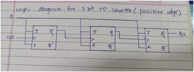
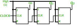
Logic Diagram for 3 bit UP counter (Negative edge)
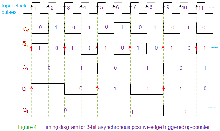
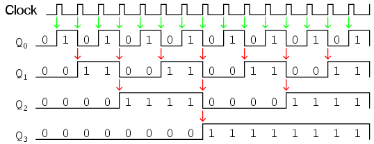
Timing Diagram for 3 bit UP counter (Negative edge)
Truth Table for 3 bit DOWN counter
Logic Diagram for 3 bit DOWN counter (Negative edge)
Timing Diagram for 3 bit DOWN counter
Draw logic diagram for mod – 6 asynchronous up counter.
Ans 1: Modulus Counters, or simply MOD counters, are defined based on the number of states that the counter will sequence through before returning back to its original value. For example, a 2-bit counter that counts from 002 to 112 in binary, that is 0 to 3 in decimal, has a modulus value of 4 ( 00 → 1 → 10 → 11, and return back to 00 ) so would therefore be called a modulo-4, or mod-4, counter. Note also that it has taken four clock pulses to get from 00 to 11.
Therefore, a “Mod-N” counter will require “N” number of flip-flops connected together to count a single data bit while providing 2n different output states, (n is the number of bits). Note that N is always a whole integer value.