3-bit Synchronous Counter
By gyaanibuddy_admin,
This is '3-bit Synchronous Counter' assignment of Digital Design - Computer Engineering of Somaiya University - Gyaani Buddy
Design of 3 bit Synchronous counter using JK flip flop
This is '3-bit Synchronous Counter' assignment of Digital Design - Computer Engineering of Somaiya University - Gyaani Buddy
Coming Soon...
A counter is a register capable of counting the number of clock pulses arriving at its clock input. Counter represents the number of clock pulses arrived. A specified sequence of states appears as counter output. This is the main difference between a register and a counter. There are two types of counter, synchronous and asynchronous. In synchronous common clock is given to all flip flop and in asynchronous first flip flop is clocked by external pulse and then each successive flip flop is clocked by Q or Q output of previous stage. Soon the clock of the second stage is triggered by the output of the first stage. Because of inherent propagation delay time all flip flops are not activated at same time which results in asynchronous operation.
Implementation Details:
Characteristic Table for 3 bit UP counter
Truth Table for 3 bit UP Counter
K Map


Logic Diagram for 3 bit UP counter

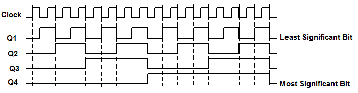
Timing Diagram for 3 bit UP counter
1. Draw logic diagram for mod-2 synchronous down counter.
Ans 1: Flip Flop Used: JK
As it is a two bit down counter , so we require 2 flip flops:
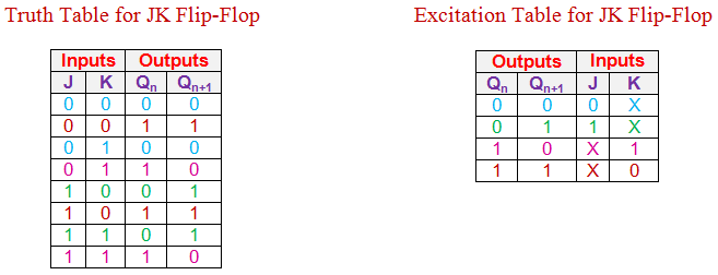
Truth Table and Excitation Table of JK Flip Flop :