4:1 Multiplexer & 1: 4 De-multiplexer
By gyaanibuddy_admin,
This is '4:1 Multiplexer & 1: 4 De-multiplexer' assignment of Digital Design - Computer Engineering of Somaiya University - Gyaani Buddy
To design and implement a 4:1 multiplexer and 1:4 de-multiplexer using logic gates and MUX IC
This is '4:1 Multiplexer & 1: 4 De-multiplexer' assignment of Digital Design - Computer Engineering of Somaiya University - Gyaani Buddy
Coming Soon...
Multiplexer: Multiplexer is a special type of combinational circuit. It is a digital circuit which selects one of the n data inputs and routes it to the output. The selection of one of the n inputs is done by the select lines. To select n inputs we require m select lines, such that 2m=n. Depending on the digital code applied at the select inputs, one out of the n data sources is selected and transmitted to a single output . E is called as the strobe or enable input which is useful for cascading. It is generally on active low terminal that means it will perform the required operation when it is low. The multiplexer act like a digitally controlled single pole, multiple way switches. The output gets connected to only one input at a time. In most of the electronic system the digital data is available on more than one line. It is necessary to route the data over a single line, under such circumstances input at a time
Types of Multiplexer:
- 2:1 Multiplexer
- 4:1 Multiplexer
- 8:1 Multiplexer
- 16:1 Multiplexer
- 32:1 Multiplexer
De-multiplexer: It has only one input, n output and m select lines. A demultiplexer performs the reverse operation of a multiplexer i.e. it receives one input and distributes it over several outputs. The demultiplexer converts a serial data signal at the input to a parallel data at its output lines. The relation between the output lines and select lines is as follows: N=2m
Types of Demultiplexers:
- 1:2 DEMUX
- 1:4 DEMUX
- 1:8 DEMUX
- 1:16 DEMUX
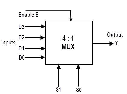
Implementation Details of 4:1 MUX
Block Diagram of 4:1 MUX


Circuit Diagram of 4:1 MUX


Truth table
From Truth Table:
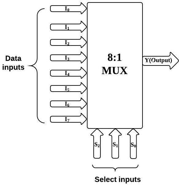
Implementation Details of 8:1 MUX
Block Diagram of 8:1 MUX
Circuit Diagram of 8:1 MUX
Truth Table for 8:1 Multiplexer

From Truth Table:

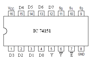
Pin diagram: IC 74151
Block Diagram of 1:4 DE MUX

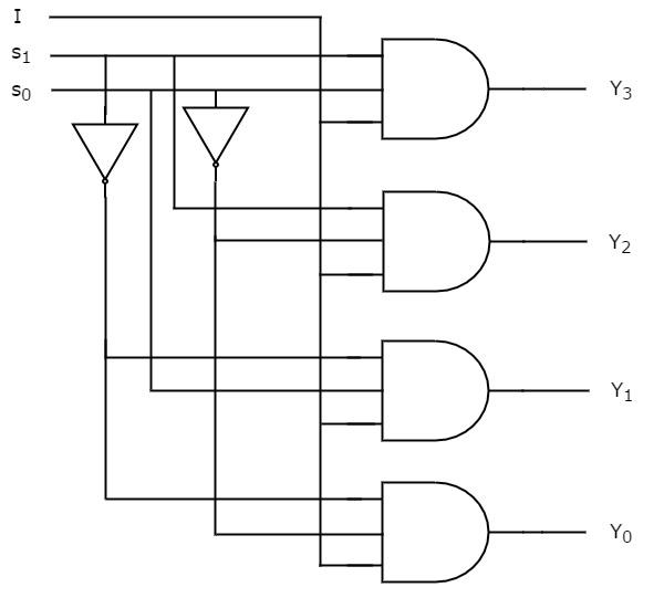
Circuit Diagram of 1:4 DE MUX
Truth Table for 1:4 Demultiplexers
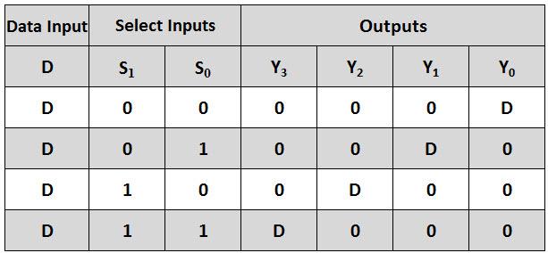
From Truth Table:

Q. How many select lines are required for 64:1 MUX?
Ans : Every multiplexer has at least one select line, which is used to select which input signal gets relayed to the output.
Formula= 2^n i.e. 2^n inputs require n input lines.
Thus for 64:1 MUX 6 select lines are required.
Q. State some applications of MUX and DEMUX.
Ans : Applications of MUX:
- Communication System – A Multiplexer is used in communication systems, which has a transmission system and also a communication network. A Multiplexer is used to increase the efficiency of the communication system by allowing the transmission of data, such as audio & video data from different channels via cables and single lines.
- Telephone Network – A multiplexer is used in telephone networks to integrate the multiple audio signals on a single line of transmission.
- Transmission from the Computer System of a Satellite: A Multiplexer is used to transmit the data signals from the computer system of a satellite to the ground system by using a GSM communication.
Applications of DE-MUX:
- Communication System – Multiplexer and Demultiplexer both are used in communication systems to carry out the process of data transmission. A De-multiplexer receives the output signals from the multiplexer; and, at the receiver end, it converts them back to the original form.
- Arithmetic Logic Unit – The output of the arithmetic logic unit is fed as an input to the De-multiplexer, and the o/p of the demultiplexer is connected to a multiple registers The output of the ALU can be stored in multiple registers.
- Serial to Parallel Converter – The serial to parallel converter is used to reform parallel data. In this method, serial data are given as an input to the De-multiplexer at a regular interval, and a counter is attached to the demultiplexer at the control i/p to sense the data signal at the demultiplexer’s o/p. When all data signals are stored, the output of the demultiplexer can be read out in parallel.
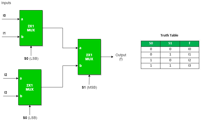
Q. Build a 4:1 MUX using only 2:1 MUX.